4.6 KiB
| path | tags | auther | auther_short | |
|---|---|---|---|---|
| /elektro/hr/rts10/ | kladjes, elektro, elektro/hr, elektro/hr/rts10 |
|
E.L.F. van Reenen |
Report Week 1.2
volatile
volatile is a keyword in c to specify to the comiler it soult not optimize the variable away. This can be usfull for debugging perpeses, if a it is used somewhere the compiler does not reconize or (for example hardwere registers). I learnd this form colleagues on my internship at Erisk.
assignment 2.2
will in line 14 and 21^[line numerbers differ from the assignment, becouse change longer lines te prevent linewrapping] to alternate the green and red with oragne and blue.
The pinout is as followed
orange: port D bit 13
green: port D bit 12
red: port D bit 14
blue: port D bit 15
Bit 12 and 14 sould start different as bit 13 and 15. Then invert all four bits every loop to achees the assignment.
I found the defines in the sourcefile where the modder defines are defined.
#include <stdint.h>
#include <stm32f4xx.h>

int main(void)
{
    // GPIO Port D Clock Enable
    RCC->AHB1ENR = RCC_AHB1ENR_GPIODEN;
    // GPIO Port D Pin 15 down to 12 Push/Pull Output
    GPIOD->MODER = GPIO_MODER_MODER12_0
                   | GPIO_MODER_MODER13_0
                   | GPIO_MODER_MODER14_0
                   | GPIO_MODER_MODER15_0;
    // Set green and red LEDs
    GPIOD->ODR = GPIO_ODR_OD12 | GPIO_ODR_OD14;
    // Do forever:
    while (1)
    {
        // Wait a moment
        for (volatile int32_t i = 0; i < 1000000; i++);
        // Flip all LEDs
        GPIOD->ODR ^= GPIO_ODR_OD12
                      | GPIO_ODR_OD13
                      | GPIO_ODR_OD14
                      | GPIO_ODR_OD15;
    }
}
How is the assambly generated for line 9 compeard to the magic value
0x55000000
The compiler regonizes that it can calculate the or opperations at compile time becouse it only used compile time defines as inputs. This reults in the foloing line of assambly.
mov.w r2, #1426063360 @ 0x55000000
assignment 2.3
skiped
assignment 2.4
skiped
assignment 2.5
Copy the project from assignment 2.2 and update the clock to use the
8 MHzexternal cristal (HSE).
I added line 6 throw 15, the rest is uncheached.
#include <stdint.h>
#include <stm32f4xx.h>

int main(void)
{
    // Enable HSE
    RCC->CR |= RCC_CR_HSEON;
    // Wait until HSE is stable
    while ((RCC->CR & RCC_CR_HSERDY) == 0);
    // Select HSE as the system clock
    RCC->CFGR |= RCC_CFGR_SW_HSE;
    // Wait until HSE used as the system clock
    while ((RCC->CFGR & RCC_CFGR_SWS_HSE ) == 0);
    // Disable HSI
    RCC->CR &= ~RCC_CR_HSION;


    // GPIO Port D Clock Enable
    RCC->AHB1ENR = RCC_AHB1ENR_GPIODEN;
    // GPIO Port D Pin 15 down to 12 Push/Pull Output
    GPIOD->MODER = GPIO_MODER_MODER12_0
                   | GPIO_MODER_MODER13_0
                   | GPIO_MODER_MODER14_0
                   | GPIO_MODER_MODER15_0;
    // Set green and red LEDs
    GPIOD->ODR = GPIO_ODR_OD12 | GPIO_ODR_OD14;
    // Do forever:
    while (1)
    {
        // Wait a moment
        for (volatile int32_t i = 0; i < 1000000; i++);
        // Flip all LEDs
        GPIOD->ODR ^= GPIO_ODR_OD12
                      | GPIO_ODR_OD13
                      | GPIO_ODR_OD14
                      | GPIO_ODR_OD15;
    }
}
I mesured the toggle time to be around 1.5 seconsds. This is what is expected.
Make use of the PLL to acheef a CPU clock of
100MHz.
First the power modules needs to be configured to allow for the hige clockspeed.
// enable power control
RCC->APB1ENR |= RCC_APB1ENR_PWREN;
// set voltage to support 100 MHz
PWR->CR |= PWR_CR_VOS_0 | PWR_CR_VOS_1;
Now the flash latancy is set. The powersupply on the board is 3V. This means there sould be 3 wait states.
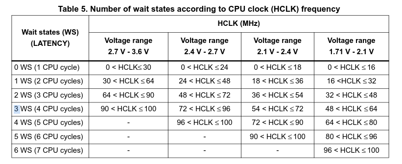
// set flash latency to support 100 MHz
FLASH->ACR |= FLASH_ACR_LATENCY_3WS;
// Wait until the wait states are used
while ((FLASH->ACR & /* ... */ ) == 0);
Finaly we configur the PLL itself.
f_{(VCO\ clock)} = f_{(PLL\ clock\ input)} \cdot (\frac{PLLN}{PLLM})
f_{(PLL\ general\ clock\ output)} = \frac{f_{(VCO\ clock)}}{PLLP}
f_{(PLL\ clock\ input)} = 8 MHz
f_{(PLL\ general\ clock\ output)} = 100 MHz
100 MHz \leq f_{(VCO\ clock)} \leq 432 MHz
PLLP \rightarrow \{2, 4, 6, 8\}
50 \leq PLLN \leq 432
2 \leq PLLM \leq 63
Becouse of the liminitan of PLLP, f_{(VCO\ clock)} can only be 200 or 400 MHz to acheve the correct f_{(PLL\ general\ clock\ output)}.
...