584 lines
16 KiB
Markdown
584 lines
16 KiB
Markdown
---
|
|
sub_title: "Real Time Systems 10"
|
|
auther:
|
|
- name: "Finley van Reenen"
|
|
email: "mail@lailatheelf.nl"
|
|
name_short: "E.L.F. van Reenen"
|
|
---
|
|
|
|
# Week 1.3
|
|
|
|
## assignment 3.1
|
|
|
|
> Base your code of `opdr_2_1.zip`.
|
|
> Configure the `SysTick` timer to set the `COUNTFLAG` in the `STK_CTRL` register every $0.5s$. Replace the for-loop with the following C code: `while (( STK_CTRL & (1 << 16)) == 0);` You have to properly define the symbol STK_CTRL yourself to make this work. Build and debug the project. If all is well, the user LEDs will blink with a frequency of $1 Hz$.
|
|
|
|
With bit 2 of `STK_CTRL` the clock source can be set. `1` for `AHB` or `0` for `AHB/8`. `AHB` is by default `HSI` witch is $16MHz$. I chose to use `AHB/8`.
|
|
|
|
$$
|
|
T = \frac{AHB/8}{f_{out}} = \frac{16\cdot 10^6/8}{2} = 10^6
|
|
$$
|
|
|
|
My resulting code^[also available at [/report-2/week_1.3/assignment_3.1/main.c](https://git.gay/LailaTheElf/RTS10_reports/src/branch/main/report-2/week_1.3/assignment_3.1/main.c)]:
|
|
|
|
```c {.numberLines}
|
|
#include <stdint.h>
|
|
|
|
#define RCC_AHB1ENR_BIT_GPIODEN *(volatile uint32_t*)(0x42000000 + 0x00023830 * 32 + 3 * 4)
|
|
#define GPIOD_BASE 0x40020C00
|
|
#define GPIOD_MODER *(volatile uint32_t*)(GPIOD_BASE + 0x00)
|
|
#define GPIOD_ODR *(volatile uint32_t*)(GPIOD_BASE + 0x14)
|
|
|
|
#define STK_CTRL *(volatile uint32_t*)(0xE000E010)
|
|
#define STK_LOAD *(volatile uint32_t*)(0xE000E014)
|
|
|
|
int main(void)
|
|
{
|
|
// GPIO Port D Clock Enable
|
|
RCC_AHB1ENR_BIT_GPIODEN = 1;
|
|
// GPIO Port D Pin 15 down to 12 Push/Pull Output
|
|
GPIOD_MODER = 0x55000000;
|
|
// Set green and red LEDs
|
|
GPIOD_ODR = 0x5000;
|
|
|
|
// SysTick enable with clk source to AHB/8
|
|
// (AHB is by default HSI; 16 MHz/8)
|
|
STK_CTRL = 1;
|
|
STK_LOAD = 1000000; // 16 MHz / 8 / 2 Hz
|
|
// Do forever:
|
|
while (1)
|
|
{
|
|
// Wait a moment
|
|
while ((STK_CTRL & (1 << 16)) == 0);
|
|
// Flip all LEDs
|
|
GPIOD_ODR ^= 0xF000;
|
|
}
|
|
}
|
|
```
|
|
|
|
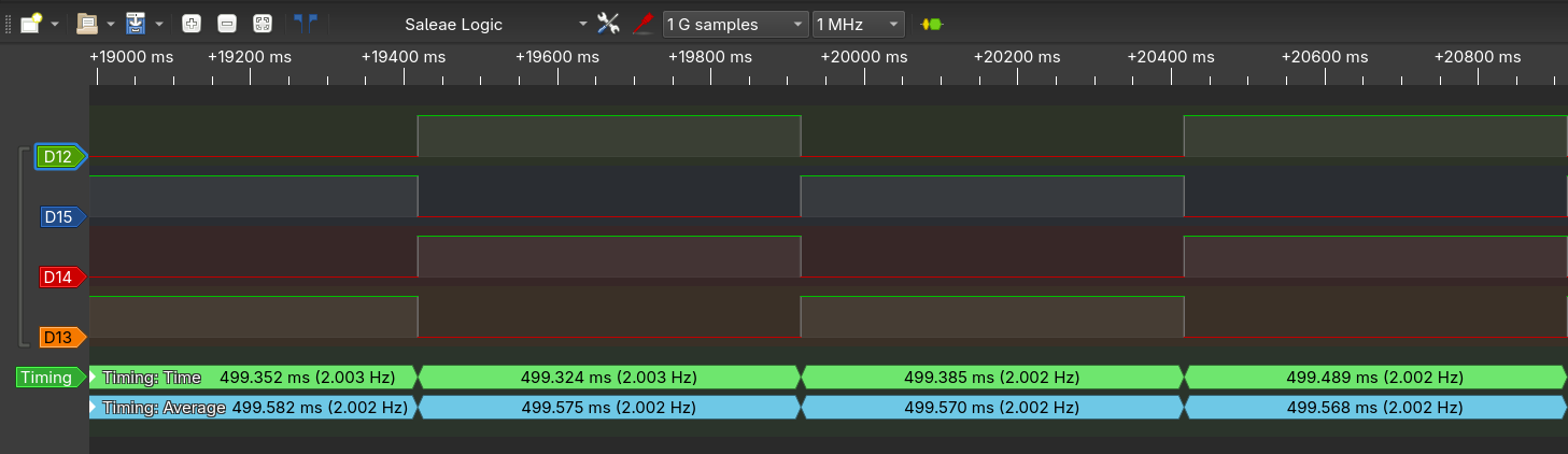
I measured the resulting frequency with an logic analyser (figure \ref{31_logic}; channels are coloured to the led colour). It measured a period time of $499.568ms$, I call this error could be my cheap logic analyser or en error in the internal oscillator.
|
|
|
|
|
|
|
|
## assignment 3.2
|
|
|
|
> Configure the SysTick timer to set the `COUNTFLAG` in the `STK_CTRL` register every $0.5s$ using the CMSIS API. Replace the for-loop with the following C code: `while ((SysTick->CTRL & (1 << 16)) == 0);` The symbol SysTick is defined in the CMSIS API. Build and debug the project. If all is well, the user LEDs will blink with a frequency of $1 Hz$.
|
|
|
|
Code also available at [/report-2/week_1.3/assignment_3.2/main.c](https://git.gay/LailaTheElf/RTS10_reports/src/branch/main/report-2/week_1.3/assignment_3.2/main.c)
|
|
|
|
```c {.numberLines}
|
|
#include <stdint.h>
|
|
#include <stm32f4xx.h>
|
|
|
|
int main(void)
|
|
{
|
|
// GPIO Port D Clock Enable
|
|
RCC->AHB1ENR = RCC_AHB1ENR_GPIODEN;
|
|
// GPIO Port D Pin 15 down to 12 Push/Pull Output
|
|
GPIOD->MODER = GPIO_MODER_MODER12_0
|
|
| GPIO_MODER_MODER13_0
|
|
| GPIO_MODER_MODER14_0
|
|
| GPIO_MODER_MODER15_0;
|
|
// Set green and red LEDs
|
|
GPIOD->ODR = GPIO_ODR_OD12 | GPIO_ODR_OD14;
|
|
|
|
// SysTick enable with clk source to AHB/8
|
|
SysTick->CTRL = SysTick_CTRL_ENABLE_Msk;
|
|
SysTick->LOAD = 1000000; // 16 MHz / 8 / 2 Hz
|
|
|
|
// Do forever:
|
|
while (1)
|
|
{
|
|
// Wait a moment
|
|
while ((SysTick->CTRL & (1 << 16)) == 0);
|
|
// Flip all LEDs
|
|
GPIOD->ODR ^= GPIO_ODR_OD12
|
|
| GPIO_ODR_OD13
|
|
| GPIO_ODR_OD14
|
|
| GPIO_ODR_OD15;
|
|
}
|
|
}
|
|
```
|
|
|
|
This time I measured $499.586ms$ with the logic analyser.
|
|
|
|
## assignment 3.3
|
|
|
|
> B) Configure the SysTick timer to generate an interrupt (also called an exception) every `0.5s`.
|
|
|
|
code also available at [/report-2/week_1.3/assignment_3.3/main.c](https://git.gay/LailaTheElf/RTS10_reports/src/branch/main/report-2/week_1.3/assignment_3.3/main.c)
|
|
|
|
```c {.numberLines}
|
|
#include <stdint.h>
|
|
#include <stdbool.h>
|
|
|
|
#define RCC_AHB1ENR_BIT_GPIODEN *(volatile uint32_t*)(0x42000000 + 0x00023830 * 32 + 3 * 4)
|
|
#define GPIOD_BASE 0x40020C00
|
|
#define GPIOD_MODER *(volatile uint32_t*)(GPIOD_BASE + 0x00)
|
|
#define GPIOD_ODR *(volatile uint32_t*)(GPIOD_BASE + 0x14)
|
|
|
|
#define STK_CTRL *(volatile uint32_t*)(0xE000E010)
|
|
#define STK_LOAD *(volatile uint32_t*)(0xE000E014)
|
|
|
|
volatile bool flag = false;
|
|
|
|
void SysTick_Handler()
|
|
{
|
|
flag = true;
|
|
}
|
|
|
|
int main(void)
|
|
{
|
|
// GPIO Port D Clock Enable
|
|
RCC_AHB1ENR_BIT_GPIODEN = 1;
|
|
// GPIO Port D Pin 15 down to 12 Push/Pull Output
|
|
GPIOD_MODER = 0x55000000;
|
|
// Set green and red LEDs
|
|
GPIOD_ODR = 0x5000;
|
|
|
|
// SysTick enable with interupt and clk source to AHB/8
|
|
STK_CTRL = (1<<1) | 1;
|
|
STK_LOAD = 1000000; // 0.5 sec / (16 MHz / 8)
|
|
// Do forever:
|
|
while (1)
|
|
{
|
|
// Wait a moment
|
|
while (!flag)
|
|
{
|
|
__asm__(" WFI"); // sleep until SysTick
|
|
}
|
|
flag = false;
|
|
// Flip all LEDs
|
|
GPIOD_ODR ^= 0xF000;
|
|
}
|
|
}
|
|
```
|
|
|
|
> C) Why must the flag variable be defined as volatile?
|
|
|
|
because the compiler doesn't know when `flag` changes. Without `volatile` optimisations can think it does not change at all.
|
|
|
|
## assignment 3.4
|
|
|
|
> Configure the SysTick timer to generate an interrupt every `0.5s`. This can be done by using the function `SysTick_Config` from the CMSIS API.
|
|
|
|
code also available at [/report-2/week_1.3/assignment_3.4/main.c](https://git.gay/LailaTheElf/RTS10_reports/src/branch/main/report-2/week_1.3/assignment_3.4/main.c)
|
|
|
|
```c {.numberLines}
|
|
#include <stdint.h>
|
|
#include <stm32f4xx.h>
|
|
#include <stdbool.h>
|
|
|
|
volatile bool flag = false;
|
|
|
|
void SysTick_Handler()
|
|
{
|
|
flag = true;
|
|
}
|
|
|
|
int main(void)
|
|
{
|
|
// GPIO Port D Clock Enable
|
|
RCC->AHB1ENR = RCC_AHB1ENR_GPIODEN;
|
|
// GPIO Port D Pin 15 down to 12 Push/Pull Output
|
|
GPIOD->MODER = GPIO_MODER_MODER12_0
|
|
| GPIO_MODER_MODER13_0
|
|
| GPIO_MODER_MODER14_0
|
|
| GPIO_MODER_MODER15_0;
|
|
// Set green and red LEDs
|
|
GPIOD->ODR = GPIO_ODR_OD12 | GPIO_ODR_OD14;
|
|
|
|
// SysTick enable with interupt and clk source to AHB/8
|
|
SysTick->CTRL = SysTick_CTRL_TICKINT_Msk | SysTick_CTRL_ENABLE_Msk;
|
|
SysTick->LOAD = 1000000; // 0.5 sec / (16 MHz / 8)
|
|
|
|
// Do forever:
|
|
while (1)
|
|
{
|
|
// Wait a moment
|
|
while (!flag)
|
|
{
|
|
__asm__(" WFI"); // sleep until SysTick
|
|
}
|
|
flag = false;
|
|
// Flip all LEDs
|
|
GPIOD->ODR ^= GPIO_ODR_OD12
|
|
| GPIO_ODR_OD13
|
|
| GPIO_ODR_OD14
|
|
| GPIO_ODR_OD15;
|
|
}
|
|
}
|
|
```
|
|
|
|
## assignment 3.5
|
|
|
|
> Now based on project opdr_3_4 create a rotation loop which simulates a simple traffic light: green (5 seconds), orange (1 second), red (4 seconds). The time each light is on must be easily adjustable with a granularity of $0.5s$. The processor must be put to sleep in between interrupts. Make use of an enumeration construct (`enum`) for the colors and a `switch`-`case`-statement for the rotation.
|
|
|
|
code also available at [/report-2/week_1.3/assignment_3.5/main.c](https://git.gay/LailaTheElf/RTS10_reports/src/branch/main/report-2/week_1.3/assignment_3.5/main.c)
|
|
|
|
```c {.numberLines}
|
|
#include <stdint.h>
|
|
#include <stm32f4xx.h>
|
|
#include <stdbool.h>
|
|
|
|
volatile bool flag = false;
|
|
|
|
void SysTick_Handler()
|
|
{
|
|
flag = true;
|
|
}
|
|
|
|
enum STATE {
|
|
STATE_GREEN,
|
|
STATE_ORANGE,
|
|
STATE_RED
|
|
};
|
|
|
|
int main(void)
|
|
{
|
|
// GPIO Port D Clock Enable
|
|
RCC->AHB1ENR = RCC_AHB1ENR_GPIODEN;
|
|
// GPIO Port D Pin 15 down to 12 Push/Pull Output
|
|
GPIOD->MODER = GPIO_MODER_MODER12_0
|
|
| GPIO_MODER_MODER13_0
|
|
| GPIO_MODER_MODER14_0
|
|
| GPIO_MODER_MODER15_0;
|
|
// Set green and red LEDs
|
|
GPIOD->ODR = GPIO_ODR_OD12;
|
|
|
|
// SysTick enable with interupt and clk source to AHB/8
|
|
SysTick->CTRL = SysTick_CTRL_TICKINT_Msk | SysTick_CTRL_ENABLE_Msk;
|
|
SysTick->LOAD = 1000000; // 0.5 sec / (8 MHz / 8)
|
|
|
|
// time of each color in half seconds
|
|
const uint32_t time_green = 10; // 5 seconds
|
|
const uint32_t time_orange = 2; // 1 seconds
|
|
const uint32_t time_red = 8; // 4 seconds
|
|
|
|
uint32_t timer = time_green;
|
|
enum STATE State = STATE_GREEN;
|
|
|
|
// Do forever:
|
|
while (1)
|
|
{
|
|
// Wait a moment
|
|
while (!flag)
|
|
{
|
|
__asm__(" WFI"); // sleep until SysTick
|
|
}
|
|
flag = false;
|
|
|
|
timer--;
|
|
if (timer == 0)
|
|
{
|
|
// turn off all leds
|
|
GPIOD->ODR &= ~(GPIO_ODR_OD12
|
|
| GPIO_ODR_OD13
|
|
| GPIO_ODR_OD14
|
|
| GPIO_ODR_OD15);
|
|
switch (State) {
|
|
case STATE_GREEN:
|
|
State = STATE_ORANGE;
|
|
GPIOD->ODR |= GPIO_ODR_OD13;
|
|
timer = time_orange;
|
|
break;
|
|
case STATE_ORANGE:
|
|
State = STATE_RED;
|
|
GPIOD->ODR |= GPIO_ODR_OD14;
|
|
timer = time_red;
|
|
break;
|
|
case STATE_RED:
|
|
State = STATE_GREEN;
|
|
GPIOD->ODR |= GPIO_ODR_OD12;
|
|
timer = time_green;
|
|
break;
|
|
}
|
|
}
|
|
}
|
|
}
|
|
```
|
|
|
|
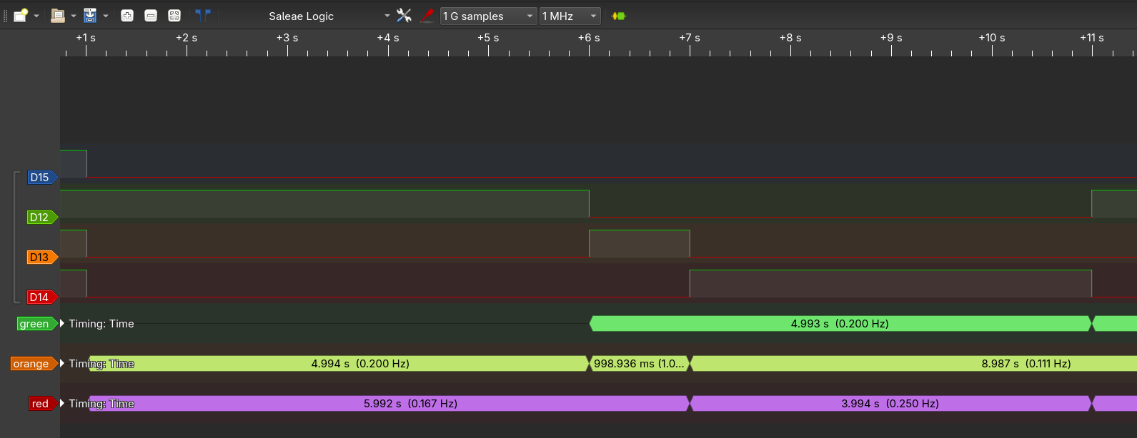
Again I validated the timings with the logic-analyser.
|
|
|
|
|
|
|
|
## assignment 3.6
|
|
|
|
> - create a copy of the previous project and rename it to opdr_3_6.
|
|
> - Using the description of this assignment, define a struct for a “task” and create a global array of 8 empty tasks.
|
|
> - Create a function `addTask(...)` to help create a task from a function pointer and other parameters, and add it to the task list (the array) at an appropriate index.
|
|
> - Create 4 functions to toggle each led separately, these are the functions that will correspond to 4 tasks.
|
|
> - Use `addTask(...)` 4 times to couple each led function to a new task in the task list with periods of: 200 ticks, 500 ticks, 750 ticks, and 300 ticks for green, orange, red, and blue respectively.
|
|
> - In the SysTick ISR, walk through the task list and decrement each of the task counters.
|
|
> - Think of, and expand on, the task struct to notify per task whether it is in a WAITING or READY state. Set the state in the ISR depending on the task counter.
|
|
> - Create a function runReadyTasks() that will walk through the task list and execute any task in the READY state. Replace your switch-case rotation in the function main with a call to this function.
|
|
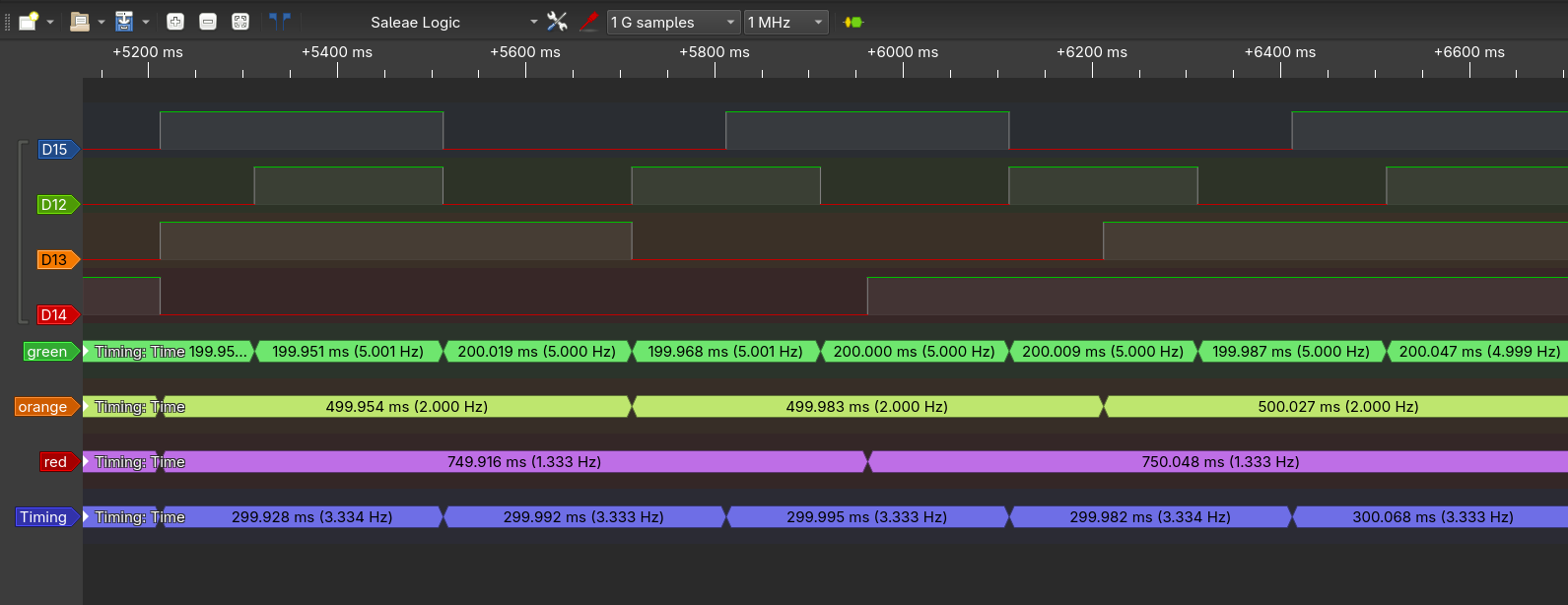
> - Make use of a logic analyzer to verify the timing of the tasks
|
|
|
|
code also available at [/report-2/week_1.3/assignment_3.6/main.c](https://git.gay/LailaTheElf/RTS10_reports/src/branch/main/report-2/week_1.3/assignment_3.6/main.c)
|
|
|
|
```c {.numberLines}
|
|
#include <stdint.h>
|
|
#include <stm32f4xx.h>
|
|
#include <stdbool.h>
|
|
|
|
volatile uint32_t ISR_Ticks = 0;
|
|
|
|
struct TASK {
|
|
void (*fn)(void);
|
|
uint32_t counter;
|
|
uint32_t counter_rst;
|
|
};
|
|
|
|
uint8_t Tasks_len = 0;
|
|
struct TASK Tasks[8];
|
|
|
|
void SysTick_Handler()
|
|
{
|
|
ISR_Ticks++;
|
|
}
|
|
|
|
bool addTask(void (*fn)(void), uint32_t counter)
|
|
{
|
|
if (Tasks_len >= 8) {
|
|
return false;
|
|
}
|
|
Tasks[Tasks_len].fn = fn;
|
|
Tasks[Tasks_len].counter = counter;
|
|
Tasks[Tasks_len].counter_rst = counter;
|
|
Tasks_len++;
|
|
return true;
|
|
}
|
|
|
|
void taskGreen()
|
|
{
|
|
GPIOD->ODR ^= GPIO_ODR_OD12;
|
|
}
|
|
|
|
void taskOrange()
|
|
{
|
|
GPIOD->ODR ^= GPIO_ODR_OD13;
|
|
}
|
|
|
|
void taskRed()
|
|
{
|
|
GPIOD->ODR ^= GPIO_ODR_OD14;
|
|
}
|
|
|
|
void taskBlue()
|
|
{
|
|
GPIOD->ODR ^= GPIO_ODR_OD15;
|
|
}
|
|
|
|
enum STATE {
|
|
STATE_GREEN,
|
|
STATE_ORANGE,
|
|
STATE_RED
|
|
};
|
|
|
|
int main(void)
|
|
{
|
|
// GPIO Port D Clock Enable
|
|
RCC->AHB1ENR = RCC_AHB1ENR_GPIODEN;
|
|
// GPIO Port D Pin 15 down to 12 Push/Pull Output
|
|
GPIOD->MODER = GPIO_MODER_MODER12_0
|
|
| GPIO_MODER_MODER13_0
|
|
| GPIO_MODER_MODER14_0
|
|
| GPIO_MODER_MODER15_0;
|
|
// Set all leds off
|
|
GPIOD->ODR = 0;
|
|
|
|
|
|
// SysTick enable with interupt and clk source to AHB/8
|
|
SysTick->CTRL = SysTick_CTRL_TICKINT_Msk | SysTick_CTRL_ENABLE_Msk;
|
|
SysTick->LOAD = 2000; // 1 ms / (16 MHz / 8)
|
|
|
|
addTask(*taskGreen, 200);
|
|
addTask(*taskOrange, 500);
|
|
addTask(*taskRed, 750);
|
|
addTask(*taskBlue, 300);
|
|
|
|
// Do forever:
|
|
while (1)
|
|
{
|
|
// Wait a moment
|
|
while (ISR_Ticks == 0)
|
|
{
|
|
__asm__(" WFI"); // sleep until SysTick
|
|
}
|
|
uint32_t ticks = ISR_Ticks;
|
|
ISR_Ticks = 0;
|
|
|
|
// decrement all counters
|
|
for (uint8_t i=0; i<Tasks_len; i++)
|
|
{
|
|
if (Tasks[i].counter > ticks)
|
|
{
|
|
Tasks[i].counter -= ticks;
|
|
}
|
|
else
|
|
{
|
|
Tasks[i].counter = 0;
|
|
}
|
|
}
|
|
|
|
// rust all tasks where the counter has run out
|
|
for (uint8_t i=0; i<Tasks_len; i++)
|
|
{
|
|
if (Tasks[i].counter == 0)
|
|
{
|
|
Tasks[i].fn();
|
|
Tasks[i].counter = Tasks[i].counter_rst;
|
|
}
|
|
}
|
|
}
|
|
}
|
|
```
|
|
|
|
|
|
|
|
## Assignment 3.7
|
|
|
|
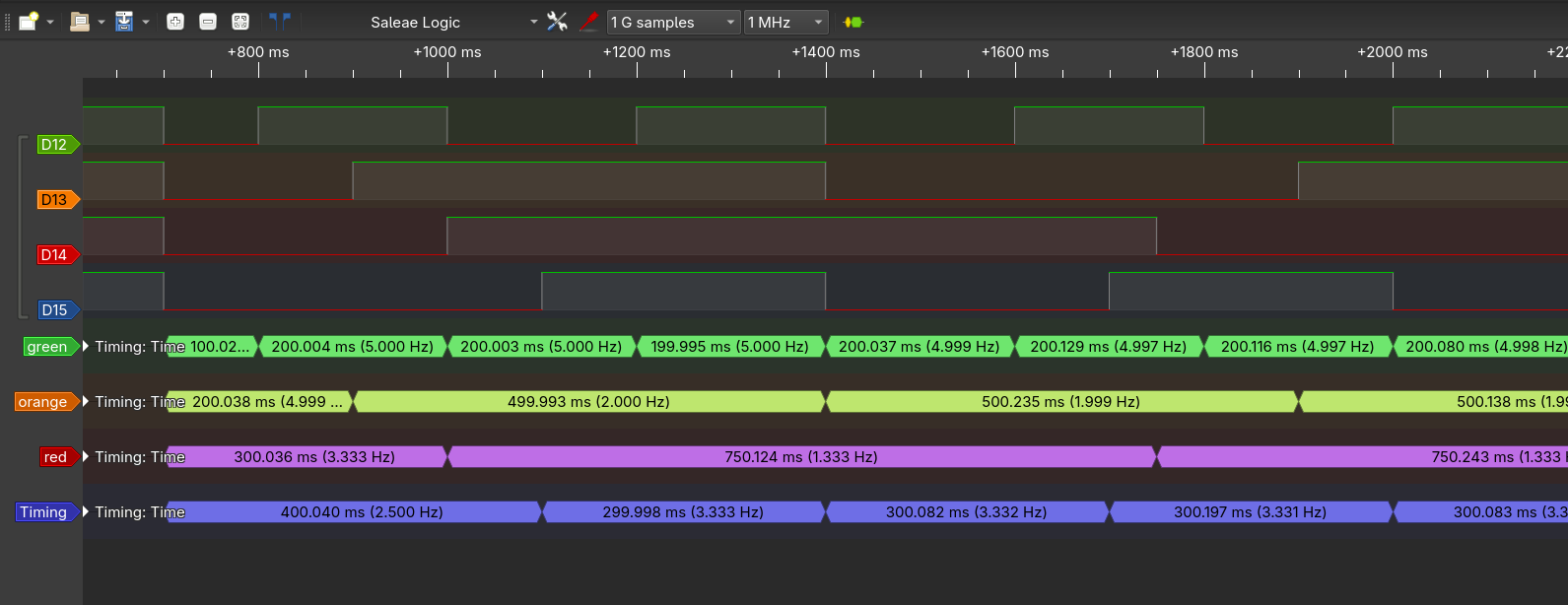
> Now add initial delays (in systicks) to your tasks. Use an initial delay of 100, 200, 300, and 400 for green, orange, red, and blue respectively. Make use of a logic analyser to verify the timing.
|
|
|
|
When A task is created, in the version of [Assignment 3.6], the following function is used:
|
|
|
|
```c
|
|
bool addTask(void (*fn)(void), uint32_t counter)
|
|
{
|
|
if (Tasks_len >= 8) {
|
|
return false;
|
|
}
|
|
Tasks[Tasks_len].fn = fn;
|
|
Tasks[Tasks_len].counter = counter;
|
|
Tasks[Tasks_len].counter_rst = counter;
|
|
Tasks_len++;
|
|
return true;
|
|
}
|
|
```
|
|
|
|
Here the `counter` and `counter_rst` members are set to the same value. `counter` is the counter that is decremented each SysClock. `counter_rst` is the value `counter` is reset to if it reacts 0 after the task is run.
|
|
|
|
Setting `counter` to the initial delay already solves this assignment. The following code implements this change.
|
|
|
|
code also available at [/report-2/week_1.3/assignment_3.7/main.c](https://git.gay/LailaTheElf/RTS10_reports/src/branch/main/report-2/week_1.3/assignment_3.7/main.c)
|
|
|
|
```c {.numberLines}
|
|
#include <stdint.h>
|
|
#include <stm32f4xx.h>
|
|
#include <stdbool.h>
|
|
|
|
volatile uint32_t ISR_Ticks = 0;
|
|
|
|
struct TASK {
|
|
void (*fn)(void);
|
|
uint32_t counter;
|
|
uint32_t counter_rst;
|
|
};
|
|
|
|
uint8_t Tasks_len = 0;
|
|
struct TASK Tasks[8];
|
|
|
|
void SysTick_Handler()
|
|
{
|
|
ISR_Ticks++;
|
|
}
|
|
|
|
bool addTask(void (*fn)(void), uint32_t counter, uint32_t counter_init)
|
|
{
|
|
if (Tasks_len >= 8) {
|
|
return false;
|
|
}
|
|
Tasks[Tasks_len].fn = fn;
|
|
Tasks[Tasks_len].counter = counter_init;
|
|
Tasks[Tasks_len].counter_rst = counter;
|
|
Tasks_len++;
|
|
return true;
|
|
}
|
|
|
|
void taskGreen()
|
|
{
|
|
GPIOD->ODR ^= GPIO_ODR_OD12;
|
|
}
|
|
|
|
void taskOrange()
|
|
{
|
|
GPIOD->ODR ^= GPIO_ODR_OD13;
|
|
}
|
|
|
|
void taskRed()
|
|
{
|
|
GPIOD->ODR ^= GPIO_ODR_OD14;
|
|
}
|
|
|
|
void taskBlue()
|
|
{
|
|
GPIOD->ODR ^= GPIO_ODR_OD15;
|
|
}
|
|
|
|
enum STATE {
|
|
STATE_GREEN,
|
|
STATE_ORANGE,
|
|
STATE_RED
|
|
};
|
|
|
|
int main(void)
|
|
{
|
|
// GPIO Port D Clock Enable
|
|
RCC->AHB1ENR = RCC_AHB1ENR_GPIODEN;
|
|
// GPIO Port D Pin 15 down to 12 Push/Pull Output
|
|
GPIOD->MODER = GPIO_MODER_MODER12_0
|
|
| GPIO_MODER_MODER13_0
|
|
| GPIO_MODER_MODER14_0
|
|
| GPIO_MODER_MODER15_0;
|
|
// Set all leds off
|
|
GPIOD->ODR = 0;
|
|
|
|
|
|
// SysTick enable with interupt and clk source to AHB/8
|
|
SysTick->CTRL = SysTick_CTRL_TICKINT_Msk | SysTick_CTRL_ENABLE_Msk;
|
|
SysTick->LOAD = 2000; // 1 ms / (16 MHz / 8)
|
|
|
|
addTask(*taskGreen, 200, 100);
|
|
addTask(*taskOrange, 500, 200);
|
|
addTask(*taskRed, 750, 300);
|
|
addTask(*taskBlue, 300, 400);
|
|
|
|
// Do forever:
|
|
while (1)
|
|
{
|
|
// Wait a moment
|
|
while (ISR_Ticks == 0)
|
|
{
|
|
__asm__(" WFI"); // sleep until SysTick
|
|
}
|
|
uint32_t ticks = ISR_Ticks;
|
|
ISR_Ticks = 0;
|
|
|
|
// decrement all counters
|
|
for (uint8_t i=0; i<Tasks_len; i++)
|
|
{
|
|
if (Tasks[i].counter > ticks)
|
|
{
|
|
Tasks[i].counter -= ticks;
|
|
}
|
|
else
|
|
{
|
|
Tasks[i].counter = 0;
|
|
}
|
|
}
|
|
|
|
// rust all tasks where the counter has run out
|
|
for (uint8_t i=0; i<Tasks_len; i++)
|
|
{
|
|
if (Tasks[i].counter == 0)
|
|
{
|
|
Tasks[i].fn();
|
|
Tasks[i].counter = Tasks[i].counter_rst;
|
|
}
|
|
}
|
|
}
|
|
}
|
|
```
|
|
|
|
|