16 KiB
| sub_title | auther | |||||||
|---|---|---|---|---|---|---|---|---|
| Real Time Systems 10 |
|
Week 1.3
assignment 3.1
Base your code of
opdr_2_1.zip.
Configure theSysTicktimer to set theCOUNTFLAGin theSTK_CTRLregister every0.5s. Replace the for-loop with the following C code:while (( STK_CTRL & (1 << 16)) == 0);You have to properly define the symbol STK_CTRL yourself to make this work. Build and debug the project. If all is well, the user LEDs will blink with a frequency of1 Hz.
With bit 2 of STK_CTRL the clock source can be set. 1 for AHB or 0 for AHB/8. AHB is by default HSI witch is 16MHz. I chose to use AHB/8.
T = \frac{AHB/8}{f_{out}} = \frac{16\cdot 10^6/8}{2} = 10^6
My resulting code^[also available at /report-2/week_1.3/assignment_3.1/main.c]:
#include <stdint.h>

#define RCC_AHB1ENR_BIT_GPIODEN *(volatile uint32_t*)(0x42000000 + 0x00023830 * 32 + 3 * 4)
#define GPIOD_BASE 0x40020C00
#define GPIOD_MODER *(volatile uint32_t*)(GPIOD_BASE + 0x00)
#define GPIOD_ODR   *(volatile uint32_t*)(GPIOD_BASE + 0x14)

#define STK_CTRL *(volatile uint32_t*)(0xE000E010)
#define STK_LOAD *(volatile uint32_t*)(0xE000E014)

int main(void)
{
    // GPIO Port D Clock Enable
    RCC_AHB1ENR_BIT_GPIODEN = 1;
    // GPIO Port D Pin 15 down to 12 Push/Pull Output
    GPIOD_MODER = 0x55000000;
    // Set green and red LEDs
    GPIOD_ODR = 0x5000;

    // SysTick enable with clk source to AHB/8
    // (AHB is by default HSI; 16 MHz/8)
    STK_CTRL = 1;
    STK_LOAD = 1000000; // 16 MHz / 8 / 2 Hz
    // Do forever:
    while (1)
    {
        // Wait a moment
        while ((STK_CTRL & (1 << 16)) == 0);
        // Flip all LEDs
        GPIOD_ODR ^= 0xF000;
    }
}
I measured the resulting frequency with an logic analyser (figure \ref{31_logic}; channels are coloured to the led colour). It measured a period time of 499.568ms, I call this error could be my cheap logic analyser or en error in the internal oscillator.
assignment 3.2
Configure the SysTick timer to set the
COUNTFLAGin theSTK_CTRLregister every0.5susing the CMSIS API. Replace the for-loop with the following C code:while ((SysTick->CTRL & (1 << 16)) == 0);The symbol SysTick is defined in the CMSIS API. Build and debug the project. If all is well, the user LEDs will blink with a frequency of1 Hz.
Code also available at /report-2/week_1.3/assignment_3.2/main.c
#include <stdint.h>
#include <stm32f4xx.h>

int main(void)
{
    // GPIO Port D Clock Enable
    RCC->AHB1ENR = RCC_AHB1ENR_GPIODEN;
    // GPIO Port D Pin 15 down to 12 Push/Pull Output
    GPIOD->MODER = GPIO_MODER_MODER12_0
                   | GPIO_MODER_MODER13_0
                   | GPIO_MODER_MODER14_0
                   | GPIO_MODER_MODER15_0;
    // Set green and red LEDs
    GPIOD->ODR = GPIO_ODR_OD12 | GPIO_ODR_OD14;

    // SysTick enable with clk source to AHB/8
    SysTick->CTRL = SysTick_CTRL_ENABLE_Msk;
    SysTick->LOAD = 1000000; // 16 MHz / 8 / 2 Hz

    // Do forever:
    while (1)
    {
        // Wait a moment
        while ((SysTick->CTRL & (1 << 16)) == 0);
        // Flip all LEDs
        GPIOD->ODR ^= GPIO_ODR_OD12
                      | GPIO_ODR_OD13
                      | GPIO_ODR_OD14
                      | GPIO_ODR_OD15;
    }
}
This time I measured 499.586ms with the logic analyser.
assignment 3.3
B) Configure the SysTick timer to generate an interrupt (also called an exception) every
0.5s.
code also available at /report-2/week_1.3/assignment_3.3/main.c
#include <stdint.h>
#include <stdbool.h>

#define RCC_AHB1ENR_BIT_GPIODEN *(volatile uint32_t*)(0x42000000 + 0x00023830 * 32 + 3 * 4)
#define GPIOD_BASE 0x40020C00
#define GPIOD_MODER *(volatile uint32_t*)(GPIOD_BASE + 0x00)
#define GPIOD_ODR   *(volatile uint32_t*)(GPIOD_BASE + 0x14)

#define STK_CTRL *(volatile uint32_t*)(0xE000E010)
#define STK_LOAD *(volatile uint32_t*)(0xE000E014)

volatile bool flag = false;

void SysTick_Handler()
{
    flag = true;
}

int main(void)
{
    // GPIO Port D Clock Enable
    RCC_AHB1ENR_BIT_GPIODEN = 1;
    // GPIO Port D Pin 15 down to 12 Push/Pull Output
    GPIOD_MODER = 0x55000000;
    // Set green and red LEDs
    GPIOD_ODR = 0x5000;

    // SysTick enable with interupt and clk source to AHB/8
	STK_CTRL = (1<<1) | 1;
    STK_LOAD = 1000000; // 0.5 sec / (16 MHz / 8)
    // Do forever:
    while (1)
    {
        // Wait a moment
        while (!flag)
        {
            __asm__("    WFI"); // sleep until SysTick
        }
        flag = false;
        // Flip all LEDs
        GPIOD_ODR ^= 0xF000;
    }
}
C) Why must the flag variable be defined as volatile?
because the compiler doesn't know when flag changes. Without volatile optimisations can think it does not change at all.
assignment 3.4
Configure the SysTick timer to generate an interrupt every
0.5s. This can be done by using the functionSysTick_Configfrom the CMSIS API.
code also available at /report-2/week_1.3/assignment_3.4/main.c
#include <stdint.h>
#include <stm32f4xx.h>
#include <stdbool.h>

volatile bool flag = false;

void SysTick_Handler()
{
    flag = true;
}

int main(void)
{
    // GPIO Port D Clock Enable
    RCC->AHB1ENR = RCC_AHB1ENR_GPIODEN;
    // GPIO Port D Pin 15 down to 12 Push/Pull Output
    GPIOD->MODER = GPIO_MODER_MODER12_0
                   | GPIO_MODER_MODER13_0
                   | GPIO_MODER_MODER14_0
                   | GPIO_MODER_MODER15_0;
    // Set green and red LEDs
    GPIOD->ODR = GPIO_ODR_OD12 | GPIO_ODR_OD14;

    // SysTick enable with interupt and clk source to AHB/8
    SysTick->CTRL = SysTick_CTRL_TICKINT_Msk | SysTick_CTRL_ENABLE_Msk;
    SysTick->LOAD = 1000000; // 0.5 sec / (16 MHz / 8)

    // Do forever:
    while (1)
    {
        // Wait a moment
        while (!flag)
        {
            __asm__("    WFI"); // sleep until SysTick
        }
        flag = false;
        // Flip all LEDs
        GPIOD->ODR ^= GPIO_ODR_OD12
                      | GPIO_ODR_OD13
                      | GPIO_ODR_OD14
                      | GPIO_ODR_OD15;
    }
}
assignment 3.5
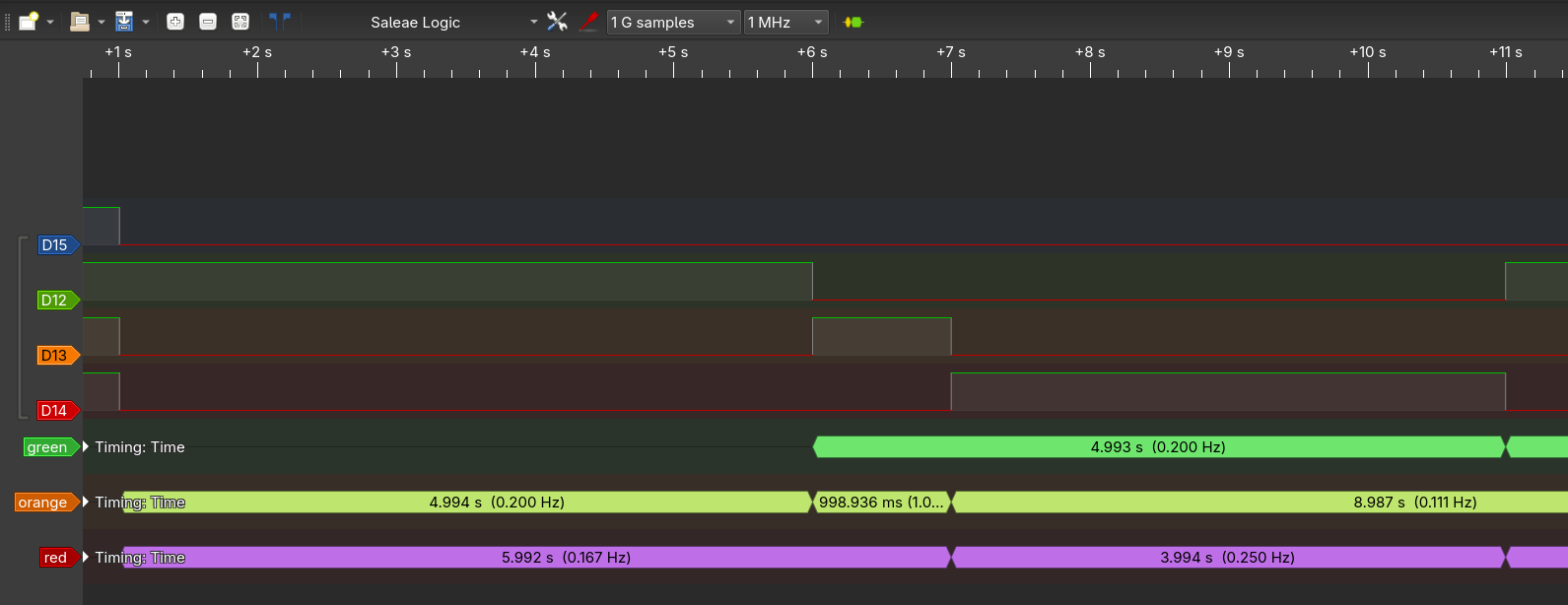
Now based on project opdr_3_4 create a rotation loop which simulates a simple traffic light: green (5 seconds), orange (1 second), red (4 seconds). The time each light is on must be easily adjustable with a granularity of
0.5s. The processor must be put to sleep in between interrupts. Make use of an enumeration construct (enum) for the colors and aswitch-case-statement for the rotation.
code also available at /report-2/week_1.3/assignment_3.5/main.c
#include <stdint.h>
#include <stm32f4xx.h>
#include <stdbool.h>

volatile bool flag = false;

void SysTick_Handler()
{
    flag = true;
}

enum STATE {
    STATE_GREEN,
    STATE_ORANGE,
    STATE_RED
};

int main(void)
{
    // GPIO Port D Clock Enable
    RCC->AHB1ENR = RCC_AHB1ENR_GPIODEN;
    // GPIO Port D Pin 15 down to 12 Push/Pull Output
    GPIOD->MODER = GPIO_MODER_MODER12_0
                   | GPIO_MODER_MODER13_0
                   | GPIO_MODER_MODER14_0
                   | GPIO_MODER_MODER15_0;
    // Set green and red LEDs
    GPIOD->ODR = GPIO_ODR_OD12;

    // SysTick enable with interupt and clk source to AHB/8
    SysTick->CTRL = SysTick_CTRL_TICKINT_Msk | SysTick_CTRL_ENABLE_Msk;
    SysTick->LOAD = 1000000; // 0.5 sec / (8 MHz / 8)

    // time of each color in half seconds
    const uint32_t time_green = 10; // 5 seconds
    const uint32_t time_orange = 2; // 1 seconds
    const uint32_t time_red = 8; // 4 seconds

    uint32_t timer = time_green;
    enum STATE State = STATE_GREEN;

    // Do forever:
    while (1)
    {
        // Wait a moment
        while (!flag)
        {
            __asm__("    WFI"); // sleep until SysTick
        }
        flag = false;

        timer--;
        if (timer == 0)
        {
            // turn off all leds
            GPIOD->ODR &= ~(GPIO_ODR_OD12
                            | GPIO_ODR_OD13
                            | GPIO_ODR_OD14
                            | GPIO_ODR_OD15);
            switch (State) {
                case STATE_GREEN:
                    State = STATE_ORANGE;
                    GPIOD->ODR |= GPIO_ODR_OD13;
                    timer = time_orange;
                    break;
                case STATE_ORANGE:
                    State = STATE_RED;
                    GPIOD->ODR |= GPIO_ODR_OD14;
                    timer = time_red;
                    break;
                case STATE_RED:
                    State = STATE_GREEN;
                    GPIOD->ODR |= GPIO_ODR_OD12;
                    timer = time_green;
                    break;
            }
        }
    }
}
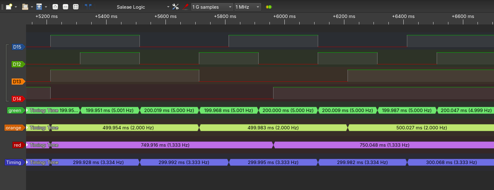
Again I validated the timings with the logic-analyser.
assignment 3.6
- create a copy of the previous project and rename it to opdr_3_6.
- Using the description of this assignment, define a struct for a “task” and create a global array of 8 empty tasks.
- Create a function
addTask(...)to help create a task from a function pointer and other parameters, and add it to the task list (the array) at an appropriate index.- Create 4 functions to toggle each led separately, these are the functions that will correspond to 4 tasks.
- Use
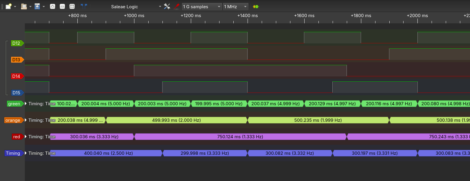
addTask(...)4 times to couple each led function to a new task in the task list with periods of: 200 ticks, 500 ticks, 750 ticks, and 300 ticks for green, orange, red, and blue respectively.- In the SysTick ISR, walk through the task list and decrement each of the task counters.
- Think of, and expand on, the task struct to notify per task whether it is in a WAITING or READY state. Set the state in the ISR depending on the task counter.
- Create a function runReadyTasks() that will walk through the task list and execute any task in the READY state. Replace your switch-case rotation in the function main with a call to this function.
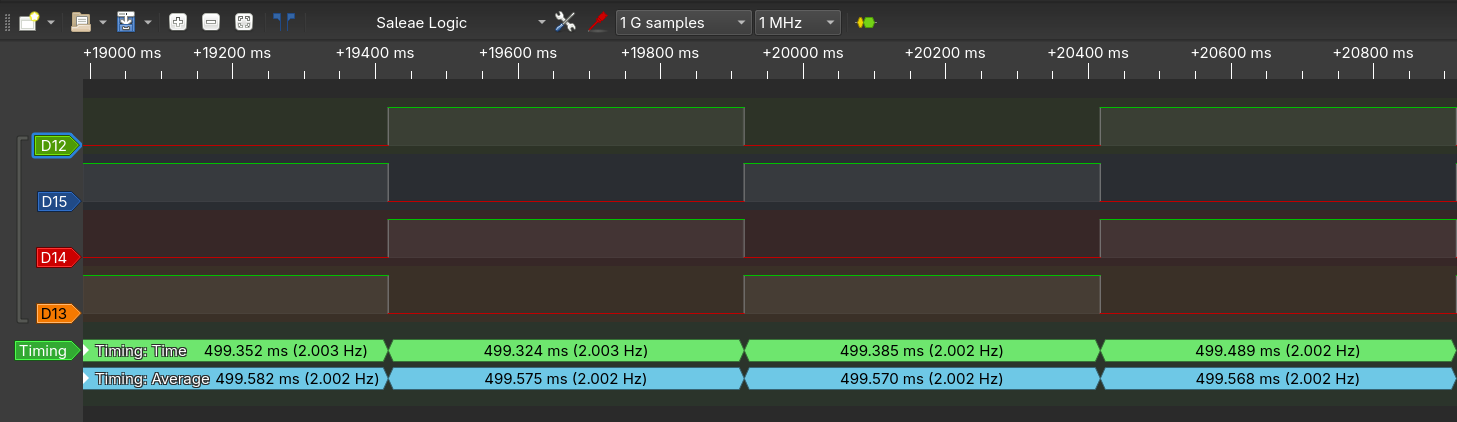
- Make use of a logic analyzer to verify the timing of the tasks
code also available at /report-2/week_1.3/assignment_3.6/main.c
#include <stdint.h>
#include <stm32f4xx.h>
#include <stdbool.h>

volatile uint32_t ISR_Ticks = 0;

struct TASK {
    void (*fn)(void);
    uint32_t counter;
    uint32_t counter_rst;
};

uint8_t Tasks_len = 0;
struct TASK Tasks[8];

void SysTick_Handler()
{
    ISR_Ticks++;
}

bool addTask(void  (*fn)(void), uint32_t counter)
{
    if (Tasks_len >= 8) {
        return false;
    }
    Tasks[Tasks_len].fn = fn;
    Tasks[Tasks_len].counter = counter;
    Tasks[Tasks_len].counter_rst = counter;
    Tasks_len++;
    return true;
}

void taskGreen()
{
    GPIOD->ODR ^= GPIO_ODR_OD12;
}

void taskOrange()
{
    GPIOD->ODR ^= GPIO_ODR_OD13;
}

void taskRed()
{
    GPIOD->ODR ^= GPIO_ODR_OD14;
}

void taskBlue()
{
    GPIOD->ODR ^= GPIO_ODR_OD15;
}

enum STATE {
    STATE_GREEN,
    STATE_ORANGE,
    STATE_RED
};

int main(void)
{
    // GPIO Port D Clock Enable
    RCC->AHB1ENR = RCC_AHB1ENR_GPIODEN;
    // GPIO Port D Pin 15 down to 12 Push/Pull Output
    GPIOD->MODER = GPIO_MODER_MODER12_0
                   | GPIO_MODER_MODER13_0
                   | GPIO_MODER_MODER14_0
                   | GPIO_MODER_MODER15_0;
    // Set all leds off
    GPIOD->ODR = 0;


    // SysTick enable with interupt and clk source to AHB/8
    SysTick->CTRL = SysTick_CTRL_TICKINT_Msk | SysTick_CTRL_ENABLE_Msk;
    SysTick->LOAD = 2000; // 1 ms / (16 MHz / 8)

    addTask(*taskGreen, 200);
    addTask(*taskOrange, 500);
    addTask(*taskRed, 750);
    addTask(*taskBlue, 300);

    // Do forever:
    while (1)
    {
        // Wait a moment
        while (ISR_Ticks == 0)
        {
            __asm__("    WFI"); // sleep until SysTick
        }
        uint32_t ticks = ISR_Ticks;
        ISR_Ticks = 0;

        // decrement all counters
        for (uint8_t i=0; i<Tasks_len; i++)
        {
            if (Tasks[i].counter > ticks)
            {
                Tasks[i].counter -= ticks;
            }
            else
            {
                Tasks[i].counter = 0;
            }
        }

        // rust all tasks where the counter has run out
        for (uint8_t i=0; i<Tasks_len; i++)
        {
            if (Tasks[i].counter == 0)
            {
                Tasks[i].fn();
                Tasks[i].counter = Tasks[i].counter_rst;
            }
        }
    }
}
Assignment 3.7
Now add initial delays (in systicks) to your tasks. Use an initial delay of 100, 200, 300, and 400 for green, orange, red, and blue respectively. Make use of a logic analyser to verify the timing.
When A task is created, in the version of [Assignment 3.6], the following function is used:
bool addTask(void  (*fn)(void), uint32_t counter)
{
    if (Tasks_len >= 8) {
        return false;
    }
    Tasks[Tasks_len].fn = fn;
    Tasks[Tasks_len].counter = counter;
    Tasks[Tasks_len].counter_rst = counter;
    Tasks_len++;
    return true;
}
Here the counter and counter_rst members are set to the same value. counter is the counter that is decremented each SysClock. counter_rst is the value counter is reset to if it reacts 0 after the task is run.
Setting counter to the initial delay already solves this assignment. The following code implements this change.
code also available at /report-2/week_1.3/assignment_3.7/main.c
#include <stdint.h>
#include <stm32f4xx.h>
#include <stdbool.h>

volatile uint32_t ISR_Ticks = 0;

struct TASK {
    void (*fn)(void);
    uint32_t counter;
    uint32_t counter_rst;
};

uint8_t Tasks_len = 0;
struct TASK Tasks[8];

void SysTick_Handler()
{
    ISR_Ticks++;
}

bool addTask(void  (*fn)(void), uint32_t counter, uint32_t counter_init)
{
    if (Tasks_len >= 8) {
        return false;
    }
    Tasks[Tasks_len].fn = fn;
    Tasks[Tasks_len].counter = counter_init;
    Tasks[Tasks_len].counter_rst = counter;
    Tasks_len++;
    return true;
}

void taskGreen()
{
    GPIOD->ODR ^= GPIO_ODR_OD12;
}

void taskOrange()
{
    GPIOD->ODR ^= GPIO_ODR_OD13;
}

void taskRed()
{
    GPIOD->ODR ^= GPIO_ODR_OD14;
}

void taskBlue()
{
    GPIOD->ODR ^= GPIO_ODR_OD15;
}

enum STATE {
    STATE_GREEN,
    STATE_ORANGE,
    STATE_RED
};

int main(void)
{
    // GPIO Port D Clock Enable
    RCC->AHB1ENR = RCC_AHB1ENR_GPIODEN;
    // GPIO Port D Pin 15 down to 12 Push/Pull Output
    GPIOD->MODER = GPIO_MODER_MODER12_0
                   | GPIO_MODER_MODER13_0
                   | GPIO_MODER_MODER14_0
                   | GPIO_MODER_MODER15_0;
    // Set all leds off
    GPIOD->ODR = 0;


    // SysTick enable with interupt and clk source to AHB/8
    SysTick->CTRL = SysTick_CTRL_TICKINT_Msk | SysTick_CTRL_ENABLE_Msk;
    SysTick->LOAD = 2000; // 1 ms / (16 MHz / 8)

    addTask(*taskGreen, 200, 100);
    addTask(*taskOrange, 500, 200);
    addTask(*taskRed, 750, 300);
    addTask(*taskBlue, 300, 400);

    // Do forever:
    while (1)
    {
        // Wait a moment
        while (ISR_Ticks == 0)
        {
            __asm__("    WFI"); // sleep until SysTick
        }
        uint32_t ticks = ISR_Ticks;
        ISR_Ticks = 0;

        // decrement all counters
        for (uint8_t i=0; i<Tasks_len; i++)
        {
            if (Tasks[i].counter > ticks)
            {
                Tasks[i].counter -= ticks;
            }
            else
            {
                Tasks[i].counter = 0;
            }
        }

        // rust all tasks where the counter has run out
        for (uint8_t i=0; i<Tasks_len; i++)
        {
            if (Tasks[i].counter == 0)
            {
                Tasks[i].fn();
                Tasks[i].counter = Tasks[i].counter_rst;
            }
        }
    }
}